


SPX17 Positive High Performance Discrete Voltage Regulator
- Product Code: SPX17
- Availability: In Stock
-
$43.60
- Ex Tax: $43.60
Download full data sheet (PDF) here.
|
Parameter |
Conditions |
Value |
Units |
|
Input voltage maximum |
|
35 |
V |
|
Output voltage positive |
variable (4*) |
+3.3 to +30 |
V |
|
Output voltage negative |
variable |
-5 to -30 |
V |
|
Output Noise |
RMS 20Hz – 20KHz (3*) |
<1 |
PPM of Vout |
|
Line Rejection |
60Hz, 1Vpp 80kHz, 1Vpp |
135 119 |
dB |
|
Continuous current |
Positive (SPX78, SPX17) |
3 |
A |
|
Maximum power dissipation (2*) |
no heat sink |
1 |
W |
|
Drop–out voltage |
Load Current 3A |
1 1.5 |
|
|
Output Impedance |
20Hz – 20KHz |
25 |
mΩ |

SPX78 and SPX79 mounted to heat sinks on a PCB
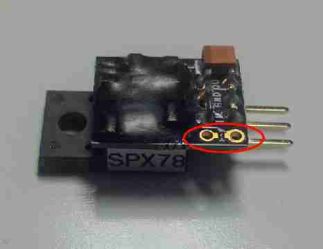
SPX with variable output is shipped with 30V out. Add a ¼W resistor between the two holes near the Rset pin to change to any Vout down to 5V. Or you can order with a standard fixed output voltage as a plug-in LM78xx replacement!
How to set output voltage of variable SPX?
SPX17, SPX78 and SPX79 are available with variable output by adding a resistor here:


When shipped, variable SPX has Vout=30V, so add a resistor to set the correct voltage before you connect it and power it on!
The only difference between variable and fixed Vout is if we add the extra resistor or if you add it. We add a thin film 0603 SMD, you can add same or a ⅛W resistor of your technology choice. The additional Rset resistor is in parallel with a 10k resistor so Vout change is not linear with Rset change. You can also add a 4th pin and put a fixed resistor or potentiometer on the main PCB. See the chart below for values.
Calculate Rset in kΩ as
![]()
Typical values are
| Vout | Rset in Ω | Nearest 1% value (Ohms) |
Nominal Vout |
| 5 | 0 | 0 | 5 |
| 6.3 | 548.52 | 549 | 6.3 |
| 7 | 869.57 | 866 | 6.99 |
| 8 | 1363.64 | 1370 | 8.01 |
| 9 | 1904.76 | 1910 | 9.01 |
| 10 | 2500 | 2490 | 9.98 |
| 12 | 3888.89 | 3900 | 12.01 |
| 12.6 | 4367.82 | 4320 | 12.54 |
| 15 | 6666.67 | 6650 | 14.98 |
| 16 | 7857.14 | 7870 | 16.01 |
| 18 | 10833.33 | 10700 | 17.92 |
| 20 | 15000 | 15000 | 20 |
| 24 | 31666.67 | 31600 | 23.99 |
| 30 | none | none | 30 |
You can use a potentiometer to set Vout. A 50k trimmer will adjust from 25.8V to 5V, a 100k trimmer will adjust from 27.7V to 5V. The trimmer is in parallel with a 10k resistor so Vout change is not linear with resistance change.
How does SPX work better than other voltage regulators?
A unique circuit, granted US patent 8294440 in 2012, uses a JFET as a voltage level shifter, allowing a precision current source and feedback loop to be powered from the quiet, clean, low noise regulator output. The precision current is used to offset the floating regulator, allowing it to work at any output voltage. For more information, read this white paper, or the patent.
Noise Comparison
How does SPX noise compare with other voltage regulators? See the noise spectra below and judge for yourself. All devices were tested with the same input supply, gain of 1000 measurement amplifier, and spectrum analyzer. All were measured as the AC component of 12VDC output, with no load. The vertical scale of all spectra was lowered by 60dB to adjust for the 1000x gain.
Baseline Test System Noise

SPX78

Belleson's SPX has very low noise, about 8µVrms across the audio band.
Sparkos Labs

Sparkos Labs SS7812 has very low noise, about 6µVrms in our test setup.
LT3045

LT3045 measures just over 2µVrms.
Dexa/NewClassD LC7812 UWB Mk2

Surprisingly, the new Dexa LC7812 UWB Mk2 measures about 110µVrms in our test setup.
TPS7A4700

Very low noise, measures about 3.5µVrms in our fixture. Its other characteristics such as output impedance and dynamic response are not very good.
SPX dynamic step response compared to newer regulators
First, why is dynamic step response important?
Dynamic step response is a measure of how a regulator output is affected by a demand for a lot of current in a short time. Ideally, output voltage does not change at all, no matter how much current is demanded, nor how fast. Unlike instant coffee, reality and the laws of physics prevent "instant" response from a voltage regulator. We can test this response using a switch to increase current demand for a short time and watch the output voltage with a fast oscilloscope to see how it responds. These comparisons are exactly that, using a 150MHz Hitachi V-1150 high speed analog oscilloscope.
Measurements are taken in the same test socket, with the same input stimulus and output sense for all devices. Measurements may differ from those you see in manufacturers' data sheets because of different setup, e.g. input or output capacitance, placement of sense device, wire lengths, etc.
Maximum output current is different for the various devices. To make it a fair test, the current step is 250mA, which is ½ the maximum for the lowest output devices. All regulators also have 100µF output capacitance and a 500Ω resistor for a 24mA DC load, which helps the trailing edge response settling time.
The LT3045 and TPS7A4700 are both surface mount monolithic devices that require a PCB to allow them to be plugged into a TO-220 style test socket. The tested devices were, when purchased, mounted on a PCB with MLCC capacitors already connected. Replacing the MLCCs with tantalum on the TPS7A4700 PCB significantly improved performance, and the measurements you see here are with 10µF tantalum.
The SPX is so fast that a ferrite bead had to be added to the pull-down transistor to prevent high frequency ringing in the response.
See the oscillograms below and judge for yourself. Top trace is the output current measured with a Tektronix current probe. The more important bottom trace is regulator output voltage, which should be perfectly flat for an ideal regulator. See notes below for more information on the tests.
Belleson SPX78 leading edge
 Belleson's new SPX settles in less than 1µsec for both leading and trailing edge of a 250mA current step.
LT3045 leading edge

Sparkos leading edge

TPS7A4700 leading edge

Dexa 2 leading edge

Belleson SPX78 trailing edge
 Belleson's new SPX settles in less than 1µsec for both leading and trailing edge of a 250mA current step.
LT3045 trailing edge

Sparkos trailing edge

TPS7A4700 trailing edge

Dexa 2 trailing edge

Ripple Rejection
Why is ripple rejection important?
Ripple rejection is a measure of how well a regulator blocks anything and everything "bad" on the input voltage from getting to its output. This is a hard requirement to meet because bad stuff can be any of
- low frequency power line voltage fluctuations
- higher frequency power line noise from other connections on the same circuit (e.g. LED bulbs or AC motors)
- frequency digital switching noise (from SMPS)
- rectifier diode off/on transient glitches
- EMI signals coupled into the circuit
- various others
Thus ripple rejection must ideally block all non-DC signals across an infinite bandwidth. While this is not possible, it is important to know how well a regulator rejects input "noise or whatever" across a broad frequency band. For audio specifically, we measured it out to 200kHz with a 150MHz bandwidth oscilloscope and a swept sine wave imposed on the regulator's input voltage.
Ripple rejection (PSRR) has been the most difficult to make of all our data sheet measurements. After making a (fourth) measurement fixture because of high frequency feed-through, we have a new set of measurements for a new generation of regulators. To read the full story, see this article on the AudioxPress web site.
Here is what we measured, where higher numbers represent better rejection, thus less ripple that gets to the regulator output:

Keep in mind that 120dBV represents 1µV and 100dBV is 10µV of ripple at the output.
The test is done as described below using ±0.5V sine wave on top of 15Vdc. Notice that SPX reduces ripple by 120dBV at 80KHz, unrivaled in the world as far as we know!
Our customers' comments that their systems sound better with Superpower are backed up by measurements—order one to hear for yourself, it really is this good.
To see all the details with spectra, see this page with comparison graphs.
The source fixture uses a DC+AC driver using an op amp servo feeding a low impedance MOSFET to deliver a good sine wave on top of a DC voltage.

We did direct comparison measurements by setting up the fixture, setting Vin and frequency and plugging in each of the regulators in turn. Testing was done with no load. A 16 bit 195K sample/second autoranging A/D was used for the FFT measurements. Measurements were made from 55Hz to 80kHz. Of course we use our regulators to power the circuitry to test our regulators!
Output Impedance
Why is output impedance (zout) important?
A power supply is a source of current from a fixed voltage. Any impedance at the power supply output (zout) is in series with the load impedance being driven by the supply. The supply impedance and the load impedance form a voltage divider, so as the load requests current from the supply, the voltage at the load will change by the amount zout * iload.
Thus lower zout delivers fundamentally better voltage regulation. Watch the first three minutes of a video from Texas Instruments to learn more [choose Low distortion design (4) and topic External sources].
SPX Output Impedance vs. Frequency
What is Superpower's output impedance? Amazing! Here is a graph of Zout vs. frequency, showing a 50mΩ maximum impedance while delivering 10mA from 20Hz to 200KHz. This is measured on a typical production SPX78 with 12V out.

What are we showing you?
In this test, a 10mA AC current is pulled from the regulator output (top trace, at 10mA/div), as frequency of the current is swept from 20Hz to 200kHz. The AC voltage appearing at the output of the regulator (bottom trace at 50mΩ/div by using a gain of 1000 amplifier) represents the output impedance, where zout=vac/iac. Voltage is graphed on an oscilloscope where you can see frequency change across the horizontal axis at 20kHz per division.
SPX zout stays low across ten times the audio band. We dare you to find or build a better regulator! Take a look at our Zout comparison page to see how SPX compares to other available voltage regulators.
Superpower Output Impedance compared to other regulators
Belleson's newest SPX regulator was multiple years in development, and designed to have the lowest possible output impedance while keeping the circuit fast and stable.
How does Superpower compare with other voltage regulators? See these oscillograms and judge for yourself. Test notes are at the bottom of the page.
Why is low zout desirable?
Output impedance, or zout, is a small signal measurement of a regulator's ability to deliver current while vout remains constant. Any deviation from constant represents a voltage drop across the output impedance due to the AC excitation current from the output.
In this test, a 10mA AC current is pulled from the regulator, as frequency of the current is swept from 20Hz to 200kHz. The AC voltage appearing at the output of the regulator represents its output impedance, where zout=vac/iac.
If you look at a power supply as a source of current from a fixed voltage, any impedance at the power supply output is in series with the load impedance being driven by the supply. That load is, for audio, typically one or many amplification devices. The supply impedance and the load impedance form a voltage divider, so as the load requests current from the supply, the voltage at the load will change by the amount zout * iload.
Thus lower supply zout delivers fundamentally better supply voltage regulation. To learn more, watch the video from TI on this page. Find Topic "Low Distortion Design" and watch the first 3 minutes of "External sources" video.
SPX78
Belleson's SPX78 has very low zout at audio frequencies and increases gradually to 50mΩ at 200kHz.
Sparkos
 zout for the Sparkos SS7812 grows to 110mΩ at 110kHz then decreases slightly toward 200kHz.
LM7812
 The LM7812 with high impedance around 10kHz and its noisy. zout is set mostly by the output capacitor.
LT3045
 The LT3045 from Analog Devices has a Zout that increases in a slight bow up to 60mΩ at 200kHz.
TPS7A4700
 The TPS7A4700 from TI has a bloom in the audio band, where zout is about 200mΩ at 10kHz.
Dexa/NewClassD LC7812 UWB Mk2
 Relatively high zout with a peak in the audio band up around 180mΩ , and visible noise.
Notes
Measurements are taken in the same test socket, with the same input stimulus and output sense for all devices. Measurements may differ from those you see in manufacturers' data sheets because of different setup, e.g. input or output capacitance, placement of sense device, wire lengths, etc.
Voltage is amplified by 500 and graphed on an oscilloscope. You can see frequency change across the horizontal axis at 20kHz per division.
The top trace is output current as measured with a Tektronix current probe amplifier set to 10mA per division. For some regulators the change in vout is too low to be useful so we fed it through our noise amplifier to give it a gain of 1000. Thus the bottom trace is 1000 x regulator Vout.
The LT3045 and TPS7A4700 are both surface mount monolithic devices that require a PCB to allow them to be plugged into a TO-220 style test socket. The tested devices were, when purchased, mounted on a PCB with MLCC capacitors already connected. Replacing the MLCCs with tantalum on the TPS7A4700 PCB significantly improved performance, and the measurements you see here are with 10µF tantalum.
It's possible that zout graphs of the lowest measured parts have some error due to feed–through in the test fixture. Thus zout could be lower than we measured.

Superpower regulator and Bel amp Components Warranty
Due to the fraught nature of circuit development, Belleson LLC cannot be liable for loss or damage to regulator or op amp components or their associated circuitry. Thus these components have no expressed or implied warranty. We work with you, our customers, as best we can to prevent problems. Please contact us with any questions or concerns prior to applying power to your circuit.
Important Legal Information
By using Belleson Superpower regulators, you agree that SPLV, SPHV, SPX, SPHP have no output protection, and a short circuit of the output to ground can damage or destroy the regulator. Also, these regulators have power dissipation limits as described in their respective datasheets, and exceeding those limits may result in damage or destruction of the device and potential damage to connected circuitry or equipment. All devices are tested prior to shipment and damaged devices will not be replaced. Belleson is not responsible for ancillary damage to associated connected components or equipment, nor liable for any related loss(es).
By using Belleson Bel amps op amps, you agree that components can be damaged by accident, misapplication or by exceeding operating or use limits.
You also agree that misuse or misapplication of Belleson products may cause damage where attempted use or application occurs, and you, as user of the product(s), or a company or corporation using the product(s), accept all responsibility for all consequences of use or application of Belleson product(s) and will not hold Belleson responsible for any damage nor injury as a result of use or attempted use of Belleson products. Belleson also is not responsible for damage to, or replacement of, equipment or components connected to or powered by Belleson products.
Belleson products are not authorized for use as critical components in life support devices or systems.
As used herein:
1. Life support devices or systems are devices or systems which, (a) are intended for surgical implant into the body, or (b) support or sustain life, and whose failure to perform when properly used in accordance with instructions for use provided in the labeling, can be reasonably expected to result in a significant injury to the user.
2. A critical component is any component of a life support device or system whose failure to perform can be reasonably expected to cause the failure of the life support device or system, or to affect its safety or effectiveness.
Copyright © Belleson LLC, all rights reserved.
Superpower Transformer Calculator
Use this calculator to decide the best transformer to use for your Superpower supply. Given the values you enter, it computes the ripple, decides the drop out voltage based on selected Superpower type and load current, sums everything and calculates the minimum Vrms of the transformer.
Calculator fields have only minimum validation so if the Vrms result has something bizarre (like "NaN"), recheck your input values. If Vrms is negative, Load current exceeds the capability of the selected Superpower type.
Heat Sink
The value in the Max heat sink °C/W box shows the maximum thermal resistance for a heat sink on a Superpower with the Vin shown in Regulator input Vpeak with the other values as given. To see the heat sink needed for a different Vin, change the value in Line Voltage Variation until the Regulator input Vpeak equals the Vin you will use in your application. The heat sink calculation assumes a 75°C temperature increase of the regulator.
Assumptions
- Linear power supply with transformer/rectifier/filter caps/Superpower
- Transformer has sufficient power that it does not sag under load (use safety margin to account for sag)
- Vdc of rectifier output is minimum value + safety margin
- Full wave center tapped rectifier follows the transformer.
For a bridge with no center tap, double the diode drop - Transformer output voltage is specified as Vrms
- Filter capacitance is entered in µF
- Select the power line frequency for your locale
- Regulator dissipation assumes nominal line voltage but allows for a drop of line variation % without losing regulation
- Rectifier diode drop allows entry of Si, SiC or other diode drop
- Heat sink allows 75°C temperature rise due to power dissipation
Special thanks to a customer whose suggestions helped us improve this calculator...you know who you are!
FAQ
How can Vrms be less than Vout?
Transformers are specified as Vrms. Full wave rectified and filtered transformer voltage is, with no load, approximately Vpeak, which is Vrms X sqrt(2). So Vrms is lower than the Vpeak required at the regulator's input, and with low output current requirements, may be lower than regulator Vout.
Why is Vrms negative and almost 1000?
The calculator does this when Load Current exceeds the capability of the selected Superpower type.
What kind of capacitors should I use for a rectifier filter?
Use the electrolytic capacitor of your choice. The most important issue for regulation is to have sufficient capacitance to prevent ripple that goes below Vout+Vdropout.
Should I bypass the filter capacitors with ceramic?
Yes, a 0.1µF ceramic cap at the Superpower Vin terminal helps reduce high frequency noise and RF. This amount or more capacitance should be placed at the Vin terminal to ground to prevent possible low level oscillation at some load current values. This does not affect the calculation very much.
How much filter capacitance should I use, can I use too much?
More filter capacitance is better, it reduces ripple. When the room lights start to dim as you switch on the power supply, you may be reaching the point of "too much." Or maybe you should run a separate mains wire for your audio system :-).
Can this calculator be used for any voltage regulator?
It can be used for any series voltage regulator if you know the drop-out voltage. For Superpower Type choose Custom regulator and enter the drop-out value for your regulator at the given load current.
NOTE! This calculator only applies to a linear transformer+rectifier+filter cap power source. It is not accurate if the raw source is a SMPS.
Use this calculator to select a suitable heat sink for your Superpower regulator. The Max Heat Sink value is the highest thermal resistance allowed for the given conditions. The bigger the thermal resistance, the smaller the heat sink.
Calculator fields have only minimum validation so if the Vrms result has something bizarre (like "NaN"), recheck your input values. If Vin is negative, Vout must also be negative, otherwise the calculations are incorrect.
Heat Sink
The value in the Max heat sink °C/W box shows the maximum thermal resistance for a heat sink on a Superpower with the given Vin. The heat sink calculation assumes a 75°C temperature increase of the regulator.
Assumptions
- Input voltage is DC or DC equivalent in Vrms
- Select SP for current < 500mA, SPJ or SPL for higher currents
- Calculator only works to 3A
- Heat sink allows 75°C temperature rise due to power dissipation
Can this calculator be used for any voltage regulator?
It can be used for any series voltage regulator if you know the drop-out voltage. For Superpower Type choose Custom regulator and enter the drop-out value for your regulator at the given load current.
Low Noise, Fast Dynamic Response, Superb Ripple Rejection, 3A Current
"The best solution is a well-designed power supply in the audio gear itself." Ed Simon's conclusion of a 5 part article on cleaning up AC power lines in AudioXpress, Aug - Dec 2008.
Now you can have the best solution! Today's 24 bit and higher circuits demand the best voltage regulation, and the Belleson Superpower gives it to you. The patented design fully isolates almost all circuitry from the input voltage, providing the best line regulation possible. The innovative design delivers current faster and cleaner than ever before available, with the lowest possible output impedance!
Bootstrap powered by its own clean, quiet output voltage, the Superpower has amazing load regulation, low noise and dynamic performance, delivering 3 Amps of output current.
You may have heard of a "super regulator" designed by noted engineer, author and audiophile circuit designer Walt Jung. Mr. Jung's design and several variations, while excellent, have been improved. Our patent is a clever and unique variation of that design that uses the regulator's own clean and quiet output voltage as the "bootstrapped" power source for its internal reference and error amplifier. Bootstrap powered by its own clean, quiet output voltage, SPX has amazing load regulation, low noise and dynamic performance, while delivering 2+ Amps of output current. Featuring
|
|
Related Products

SPLV78 1A Positive Output
SPLV78 1A Superpower Regulators, a low voltage high current regulator using a variation of our patented Belleson super regulator design. Pinout matches LM78xx and LM340 type monolithic regulators 1A output current Choose from 1.1V, 1.2V, 1.5..
SPLV17 1A Positive Output
SPLV17 1A Superpower Regulators , a low voltage high current regulator using a variation of our patented Belleson super regulator design. Pinout matches LM317 and LM1117 type monolithic regulators. 1A output current Choose from 1.1V, 1.2V, 1.5V, ..

SPLV79 1A Negative Output
SPLV79 1A Superpower Regulators, a low voltage high current regulator using a variation of our patented Belleson super regulator design. Pinout matches LM337 and LM79xx type monolithic regulators. 1A output current Choose from 1.1V, 1.2V, 1...

SPX78 Positive High Performance Discrete Voltage Regulator
Low Noise, Fast Dynamic Response, Superb Ripple Rejection, 3A Current "The best solution is a well-designed power supply in the audio gear itself." Ed Simon's conclusion of a 5 part article on cleaning up AC power lines in AudioXpress, Aug - D..

SPX79 Negative High Performance Discrete Voltage Regulator
Low Noise, Fast Dynamic Response, Superb Ripple Rejection, 2A Current "The best solution is a well-designed power supply in the audio gear itself." Ed Simon's conclusion of a 5 part article on cleaning up AC power lines in AudioXpress, Aug - D..

Bel amp High Performance Discrete JFET Input Op Amp
Bel amp—A High-Performance Discrete Op Amp Precision Amplification with Exceptional Clarity Bel amp is a premium discrete op-amp specifically engineered to deliver superior low-level signal amplification. Combining ultra-low noise, minimal distortion..